Summary: |
Interfaces with Andor CCD and EMCCD cameras. For sCMOS models such as Zyla, Neo and Sona refer to AndorSDK3. |
Authors: |
Nenad Amodaj (Windows) |
Maintainers: |
Alan Mullan (Andor) |
License: |
BSD |
Platforms: |
Windows and Linux (No Mac driver available) |
Devices: |
iXon Life, iXon Ultra, iXon3, iXon+, iXon |
Installation
Andor Driver Pack
To recognize the camera in the Windows Device Manager, install the latest Driver Pack.
On the Select Destination Location dialog, click browse and choose the current Micro-Manager installation directory. Then click Yes to confirm that you do want to install to that folder.
Disable computer power savings
Disable power saving in the BIOS. For Windows Vista and later, also disable in PCI/e power management and USB suspend saving in Power Options.
(USB only) Finding a dedicated USB bus
High-bandwidth USB cameras like iXon Life and iXon Ultra (Note Ultra and Life 888 models are USB 3.0, 897 models are USB 2.0)may lose communication during imaging if they share a USB bus with another high bandwidth USB device (like the Nikon Ti-E, some USB memory keys, etc). Plug the camera into it’s own USB bus on the computer.
Andor SRRF-Stream
***New***Andor SRRF-Stream for iXon Ultra and Life models.
Device Configuration
- Open Micromanager.
- You will be prompted to load a configuration file. To create a new configuration file use “Tools” > “Hardware Configuration Wizard…” to manually add the device.
Suggested Presets
iXon camera:
| Preset Name | Frame Transfer | Output Amplifier | Pre-Amp Gain | Readout Mode | Vertical Speed | Vertical Clock Voltage |
|---|---|---|---|---|---|---|
| EM high sensitivity | Off | Electron Multiplying | 1.70 (microseconds) | Normal | ||
| EM high speed burst mode | On | Electron Multiplying | 0.30 (microseconds) | |||
| CCD high sensitivity | Off | Conventional | 1.70 (microseconds) | Normal | ||
| CCD high capacity | Off | Conventional | 1.70 (microseconds) | Normal |
Troubleshooting (known issues and fixes)
DeviceCreate function failed
This error appears in the hardware wizard in Windows if the Andor Device Driver has just been installed, but the computer has not been restarted. Restart the computer to fix.
iXon Error 20010 DRV_ERROR_PAGELOCK
| Description | Running acquisition gives error message window: Error in device Camera: Error code 20010 (4e2a hex). See also: Corelog debug output |
|---|---|
| Cause | Bug in Andor PCI/e card driver version 4.31.0 and older. |
| Solution | Update to PCI/e driver version 4.32.0 or later (included in Andor Driver 2.94 onwards). Instructions to uninstall and install new PCI/e card driver in Appendix. |
| Andor bug number | 6659 |
iXon Pre-Amp-Gain Error Code 3
Description |
The |
|---|---|
Cause |
Bug in DeviceAdapter |
Solution |
Upgrade µManager |
Nightly build |
1.4.15_20130430 |
Affected versions |
Upto 1.4.14 |
Andor bug number |
8164 |
Clara Error 20066 PreAmp selection
Description |
Error adding camera in Hardware Configuration Wizard. See also: Listserv thread |
|---|---|
Cause |
Bug in DeviceAdapter |
Solution |
Upgrade µManager |
Nightly build |
1.4.11_20121014 |
Affected versions |
1.4.7 to 1.4.11 |
Andor bug number |
7187 |
Workaround |
Copy Andor Driver 2.90.30004.0 or older DLL to µManager directory |
Luca Error 20991
Description |
Error adding camera in Hardware Configuration Wizard. See also: Listserv thread |
|---|---|
Cause |
Bug in DeviceAdapter |
Solution |
Upgrade µManager |
Nightly build |
1.4.11_20121019 |
Affected versions |
1.4.9 to 1.4.11 |
Andor bug number |
7162 |
Workaround |
Copy Andor Driver 2.88.30002.0 or older DLL to µManager directory |
Fixing computer bus speed bottlenecks
PCIe
iXon PCIe cameras can have their live stream stops after 2 or 3 images or not start at all. The reason for this is PC motherboards throttle the PCIe speed depending on the daughter boards populated. Make sure you plug the PCIe card into a fast enough bus.
For example the Dell XPS desktop 1x PCIe bus will not run at the rated speed when the PCIe 16x graphics card is populated, so you have to instead connect the Andor PCIe card to 8x PCIe slot
PCI
iXon 885 PCI cameras can have their live stream not start at all, but will work if you bin the image 2x2 or slow the horizontal clock speed from 35MHz to 13MHz. The reason for this is a small set of PC motherboards may not fully comply with the PCI standard bandwidth, so try another motherboard (or more conveniently another computer)
USB
USB cameras using high bandwidth such as the iXon Life and Ultra must be plugged into the computer to be its own USB bus:
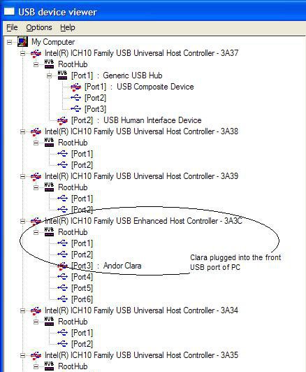
Windows USB Bus
You need to use a utility like USBview to inspect the USB bus. Try different USB slot positions on the computer until the camera is on its own USB bus.
Screenshot below of UVCview on Windows showing the Camera device (in
this example Clara) by itself on the USB bus, i.e. with no other devices
sharing it:
Linux USB Bus
You can easily check USB bus position with lsusb -t. The shell output below shows that the Clara (Vendor 0x136e Product 0x000e) has been correctly plugged into its own USB bus (Bus# 1):
$ lsusb -t
Bus#  5
 -Dev#   1 Vendor 0x1d6b Product 0x0001
Bus#  4
 -Dev#   1 Vendor 0x1d6b Product 0x0001
  |-Dev#   2 Vendor 0x046d Product 0xc045
   -Dev#   3 Vendor 0x2341 Product 0x0001
Bus#  3
 -Dev#   1 Vendor 0x1d6b Product 0x0001
   -Dev#   2 Vendor 0x03f9 Product 0x0100
Bus#  2
 -Dev#   1 Vendor 0x1d6b Product 0x0001
Bus#  1
 -Dev#   1 Vendor 0x1d6b Product 0x0002
   -Dev#   6 Vendor 0x136e Product 0x000e

$ lsusb
Bus 005 Device 001: ID 1d6b:0001 Linux Foundation 1.1 root hub
Bus 004 Device 002: ID 046d:c045 Logitech, Inc. Optical Mouse
Bus 004 Device 001: ID 1d6b:0001 Linux Foundation 1.1 root hub
Bus 003 Device 002: ID 03f9:0100 KeyTronic Corp. Keyboard
Bus 003 Device 001: ID 1d6b:0001 Linux Foundation 1.1 root hub
Bus 002 Device 001: ID 1d6b:0001 Linux Foundation 1.1 root hub
Bus 001 Device 006: ID 136e:000e
Bus 001 Device 001: ID 1d6b:0002 Linux Foundation 2.0 root hub
Resources
Development support
Please liaison with Micro-Manager developers to contact the Andor software team
Click here to search for Andor on the Micro-Manager mailing list archive.
Andor support
For contacting Andor product support regarding any questions, see under “Support” for your location - http://www.andor.com/contact_us/default.aspx
Appendix
Update Andor library (DLL)
If Micro-Manager’s Andor library is too old, adding (i.e. initializing) your Andor camera in the Hardware configuration wizard can result in:
- Error code 22
- Micro-Manager crash (with no error in the CoreLog)
To fix this, update the Andor library used by Micromanager by copying the library file from the Andor Driver Pack to your Micro-Manager installation directory:
   C:\Program Files\Andor Driver Pack 2\atmcd32d.dll
   C:\Program Files\Andor Driver Pack 2\atmcd64d.dll
Windows drivers
Install PCI/e driver
Make sure there is no yellow question mark next to the device, and that it is present in the Device Manager.
Device Type |
Appearance in Device Manager |
|---|---|
PCI/PCIe |
|
USB |
|
If there is a yellow question mark, right-click on the device, update the driver and choose:
OS |
Action |
|---|---|
Windows 7 |
|
Windows XP |
|
…and use the path:
C:\Program Files\Andor Driver Pack 2\Device Drivers\
Uninstall PCI/e card to update
- Uninstall the existing device driver for the Andor PCI/e
framegrabber card:
-
The following Microsoft guide explains who to do this, but there is no need to physically remove the card as described in step 6 of the Uninstall section:
http://technet.microsoft.com/en-us/library/cc725782.aspx#bkmk_2
- When uninstalling, make sure to select
Delete the driver software for this device. - Use
Scan for Hardware ChangesAction in the Device Manager as described in the guide. If it finds the driver, repeat this uninstall process until all copies of the driver are deleted.
-
- Upgrade to Andor camera Driver.
- Windows now uses the new
sysfile. - Restart Windows twice. After the first restart you see a yellow question mark next to the driver in the Device Manager saying the driver failing to load (Code 31). Restarting Windows the second time clears this error.
Description of Device Settings
Pre-Amplifier Gain (PAG)
-
It’s best to think of Pre-Amplifier Gain as follows:
4x = High sensitivity mode (use for EM gain)
2x = Intermediate sensitivity / capacity mode
1x = High capacity mode
For EMCCDs, Andor’s nomenclature of PAG is confusing since one may think this pre- amplification happens before EM gain amplification. In reality, EM amplification happens on sensor, and PAG happens after readout of your sensor and before digitization.
- PAG multipliers like 1x, 2x, 4x can vary between cameras since they are tuned for each sensor, e.g. for a particular camera the values could be 1x, 2.4x, 4.9x
- PAG can affect the saturation limit of your image. To determine the expected digital saturation limit, consult your camera performance sheet of your camera. Divide the “Saturation Signal per Pixel (Electrons/pixel)” by the “CCD Sensitivity (Electrons/A2D count)” to get saturation signal in digital counts.
Warning|Always set PAG to maximum High sensitivity mode when using EM gain. Lower settings of PAG is useful in Life Sciences only in Conventional (non-EM) mode
Electron Multiplying Gain (EM Gain)
EMgain range
- EMgain does not start at 1 for all cameras. The start level is tuned for each EMCCD chip.
- The actual EM gain range depends on the model of your camera: it can be from 0 to 255 (non-linear), 4096 (non-linear), or RealGain 1000 (linear)
EMgain slew rate
Warning|Typically EM gain levels should not be made to change during an experiment. The software and camera has no problem in changing the level, but there is a 1-3 second delay for the new gain value to come into effect which affects data.
e.g. if you are imaging confocal fluorescence data and DIC, and you need lower or no EM gain for DIC, one would need a 3 second delay before and after the DIC image to allow for EM gain to slew. |}
- iXon, iXon+, Luca-R and Luca-S
- EM gain circuitry is powered by a high +53V voltage rail and the gain applied to the EM readout register is proportional to this voltage.
- Thus when you increase or decrease the EM gain on the camera, you have to wait for the voltage slew to stabilize at the new set value.
- This is typically about 1-2 seconds, the maximum time being from setting EM gain from 0 to the maximum value of 1000.
- Thus it is much better to vary exposure times or excitation signal intensity rather than switching EM gain levels in a multi-channel acquisition (unless you know what you are doing)
iXon Conventional CCD or EM-CCD mode
- With the exception of the 885, you can switch between CCD and EMCCD modes via the Output_Amplifier setting
- EMCCD readout without EM gain is more noisy (~40e read noise) so Conventional readout (~6e read noise) is beneficial if light levels do not require EM gain.
- Benefits of EM gain combating the EMCCD readout register noise of ~40e can be seen from 45x onward, i.e it is better to use 45x EM gain and upward.
iCam
- Allows for rapid switching of exposure times in multi-channel acquisitions.
- µManager needs to implement SequenceExposure functions to use this feature. No camera DeviceAdapter implements this yet.
Cooling
- iXon cameras MUST be cooled to the specified temperature: at least -60 C for DV models and -70 C for DU models.
- Offset (“Baseline”) is optimal at this setting. If the camera is not cooled, the offset can be display as 0 data counts.
- Some blemishes are compensated at the specified temperature setting and will be more visible at warmer temperatures.
- No need to warm up cameras before shutdown of software and computer (since condensation does not occur).
- Full gain will not be achievable without cooling.
- EMgain is temperature compensated for RealGain cameras.
- Clara must be cooled to the specified temperature: -45 C with fan, -15 C without. The Clara-E is fixed at cooling to -20 C, so no action is needed to set its temperature
Force Run till Abort
This can be turned on in the Device Property Browser (“On” or “Off”; Default “Off”). The purpose of this is to allower users to acquire Multi-Dimensional Acquisitions with a large number of Time points. Selecting “On” will force the acquisition mode into Run till abort. This prevents the sdk from trying to lock the full size of the acquistion in memeory (for large number of Time points this is too much memory). The sdk uses an internal circular buffer to acquire the images.
When forcing the acquisition mode into Run till abort it is expected that there will be an incorrect number of Fire Pulses generated.
Frame Transfer (should actually be called “overlap”)
Frame transfer refers to the captured image getting transferred to a masked pixel array storage area (quick step) so it can be read out from there (slow step). The real benefit of FT comes when overlap is applied, so that a new image can be captured while the previous is read out. The confusing thing is that the FT step actually always occurs, whether “FT” is on or off in uM. That setting only changes whether overlap is on or off (if off, the sensor is in keep clean mode while the FT chip is read out). Since the readout register is after the FT chip, the image always gets transferred to the storage area. So think of the FT setting in uM as really “overlap.”
Triggering
See details on triggering at Andor: http://www.andor.com/learning-academy/trigger-modes-ixon-ultra-and-ixon3-trigger-modes
(See details on controlling two cameras simultaneously using the Multi-Camera utility here: https://micro-manager.org/wiki/Utilities#Multi-Camera and below: https://micro-manager.org/wiki/Andor#Dual_camera_setup)
Software vs internal
Internal is the basic triggering mode, where the camera decides when to start the acquisition after receiving a signal from the software. “On receipt of the Start command from the PC, the camera completes the current Keep Clean Cycle and then performs sufficient vertical shifts to ensure that the Image and Storage regions are completely free of charge. The camera then starts its real exposure.” [iXon manual] There are no keep clean cycles between frames when in FT/overlap mode.
Software trigger mode is similar to internal but waits for a specific software trigger command from the PC before exposure. This is useful when the timing between exposures isn’t exactly known. A keep clean cycle must still complete before the first trigger.
So Software is for snaps separated by time and Internal is for a continuous sequence of exposures. For Snap, Software trigger is used by default. Internal is used for Live and MDA. (All other modes use the same for Snap and Live/MDA.) https://sourceforge.net/p/micro-manager/mailman/micro-manager-general/thread/B890316D-D8B1-4712-8E37-A2116C867036%40ucsf.edu/
External vs. Fast External
The only difference is that normal External trigger will not accept an external trigger signal until the current keep clean cycle ends. Fast External does not wait and accepts a trigger signal even if the keep clean cycle hasn’t ended. This only applies to the first frame, and once a trigger signal is accepted, there is no difference in the timing between the two modes. Because the image area is not cleaned between trigger events, the effective exposure time is the time between events.
NOTE: There is no readout after the first trigger, so the first frame should be dark.
With FT/overlap off, External (and Fast External) modes do have a keep clean cycle after the readout, so the exposure time is determined by the programmed exposure time, not the time between events. Fast External in non-FT is only good when the background light is low, otherwise the background will vary dramatically between frames (if sufficient keep clean cycles have not finished by the time the next triggering event occurs).
External Start
The trigger starts the sequence. Once the single external trigger has occurred, the camera switches to internal triggering and acquires the sequence.
External Exposure
The exposure time is determined by the width of the trigger signal pulse: exposure period starts at the rising edge and stops at the falling edge.
With FT/overlap on, the rising edge can occur during the readout of the previous frame. But if the falling edge occurs before the previous readout is complete, that signal is ignored and the exposure continues until the next falling edge. This overlap mode requires Global Clear function of the chip, only on 885 cameras.
With FT/overlap off, the readout must complete before the next rising edge can start another exposure (?).
Snap Image timing mode in uM: Delay for Exposure vs. Wait for Readout
???
Recommended settings for iXon Ultras (Use the Multi-Andor control plugin)
Continuous high speed imaging with no delay between frames (“burst”)
FT/overlap on, main in Software, peripheral in External Start, exposure time the same
(alternative: FT/overlap on, main in Software, peripheral in External, exposure of peripheral set to 0)
Simultaneous capture but with time-lapse or multiple channels with sufficient delay between frames for readout to occur
FT/overlap off, main in Software, peripheral in Fast External (or External), exposure time shorter than the triggering interval
Dual camera setup
The main resource for setting up multiple cameras is discussed on the Utility > Multi-Camera DeviceAdapter page. This section supplements that information with Andor-specific screenshots and instructions.
When you add your Andor camera in the Hardware Configuration Wizard, you should see a drop-down menu that allows you to select the camera serial number. If you do not see more than 1 serial number in the drop-down you should make sure all your cameras are present in the Device Manager. The screenshot below shows 2 iXon USB cameras:

Since these cameras are USB, we also have to make sure they are on separate USB host buses:

Start Micro-Manager with a blank configuration and add your first camera using one serial number:
.")
Then add the the Andor camera again, making sure to change the serial number to the other camera in the serial number drop-down:
.")
Add the Multi-Camera Device Adapter under Utilities so that the final list looks like this:
.")
Complete your configuration in the Wizard then look at the default Device Properties in your Device/Property Browser. The Multi-Camera device defaults to “Unknown Camera” so it is not yet usable:

You need to set these to your 2 Andor cameras:

Set your core-camera to multi-camera, to test the result:

Now when you go live or snap an image you should see the channels overlayed in your preview window.

Discussion page for Andor imported from old wiki